
Acquire the system which will enhance your business
Video
Laserscan
ELECTRODE AND NIPPLE INSPECTION LINE
ELECTRODE INSPECTION LINE: HOW IT WORKS
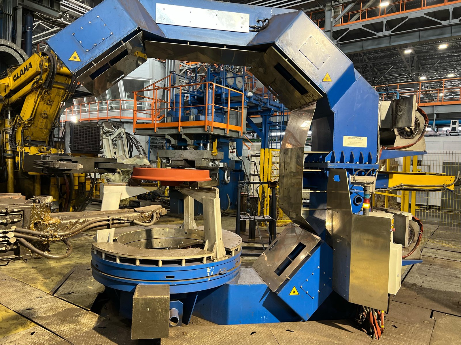
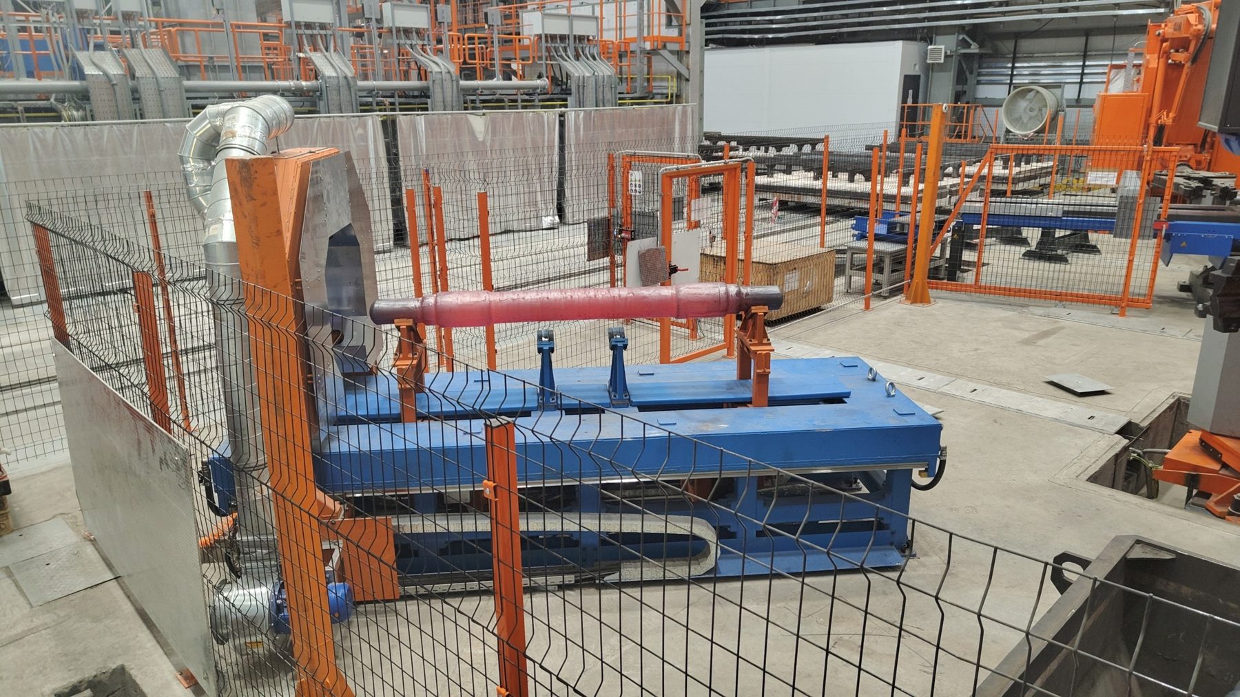
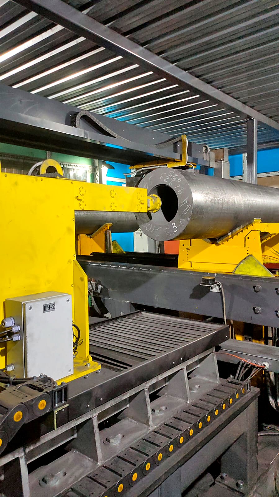
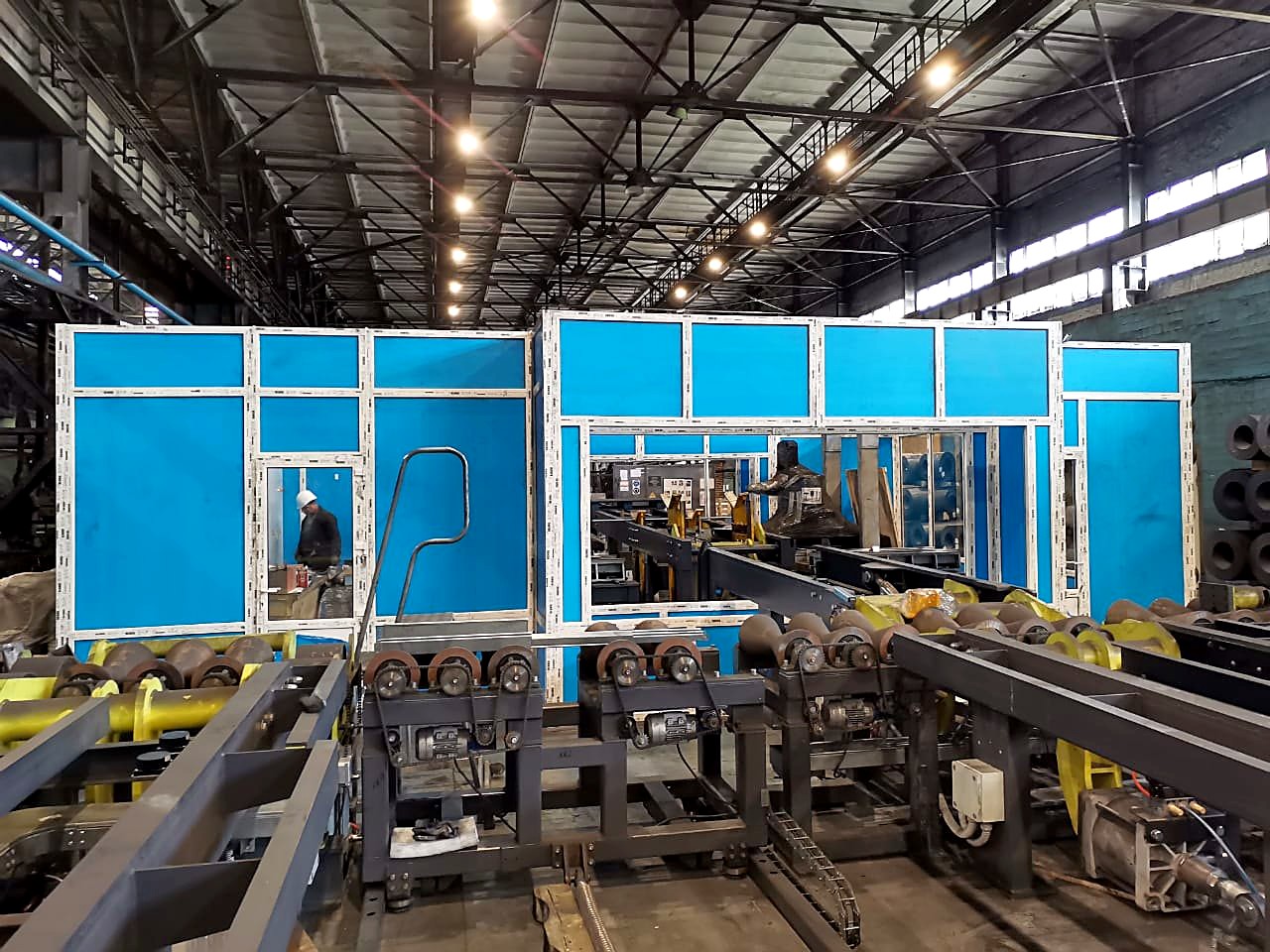
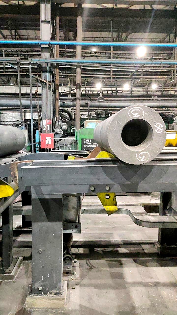
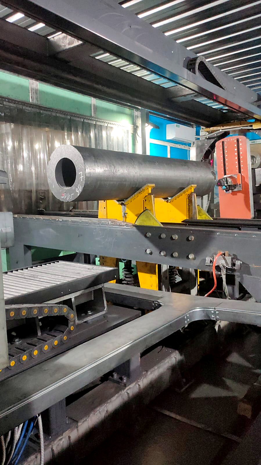
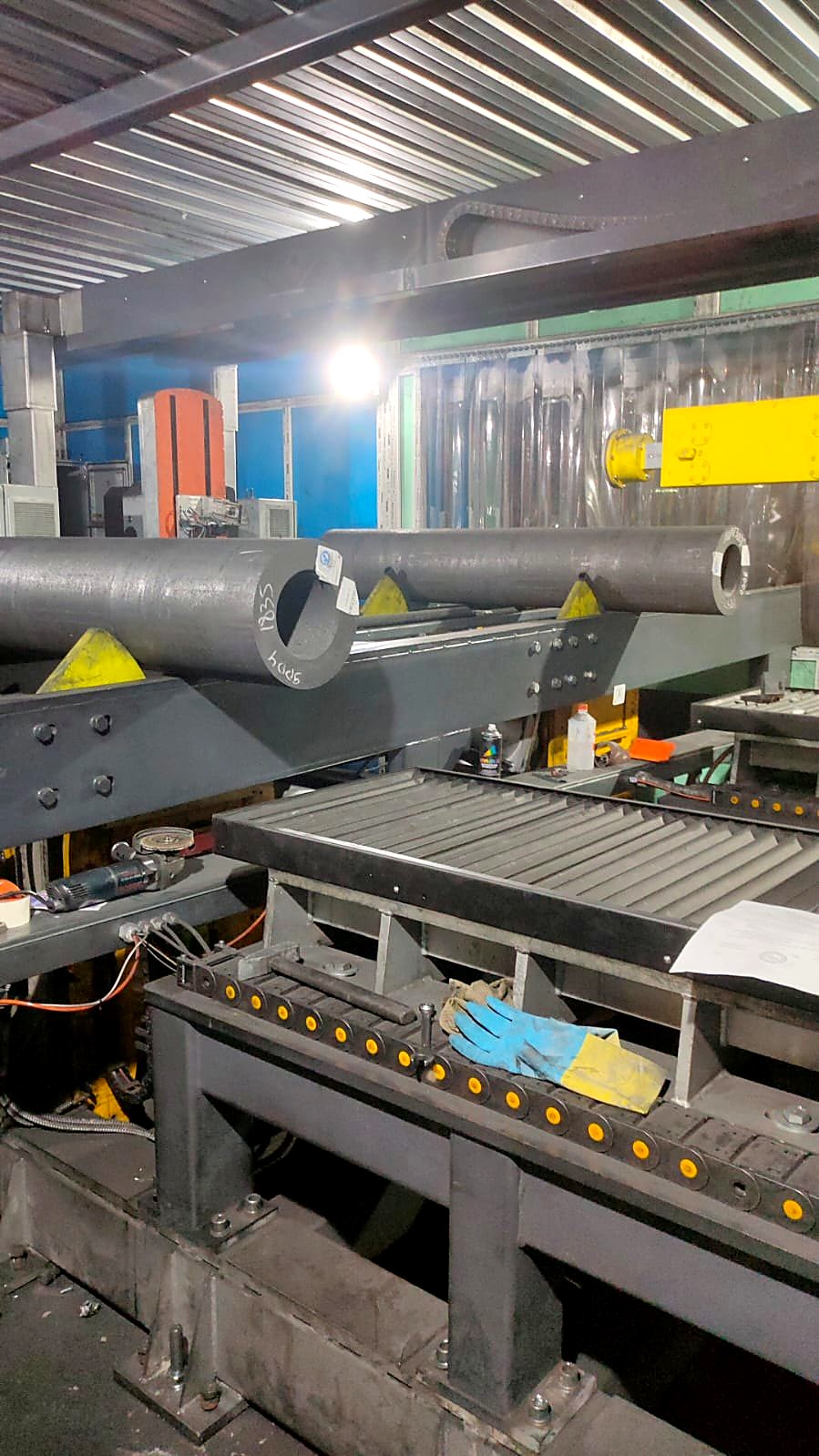
Electrodes are loaded onto the receiving rack by crane (in bundles) or straight from the machining line, then fed one at a time into an enclosed measuring box. Bar codes are read automatically to queue each electrode for inspection; without bar codes, the operator enters electrode numbers at a console.
An aligner centres each electrode on the line axis and roughly measures its diameter and length, so every measuring position adapts to the next electrode in advance. This shortens the cycle and stops an electrode of the wrong size from entering the box and damaging the equipment. A pair of jacks at each position aligns electrodes of every size with the measuring systems, with no changeover.
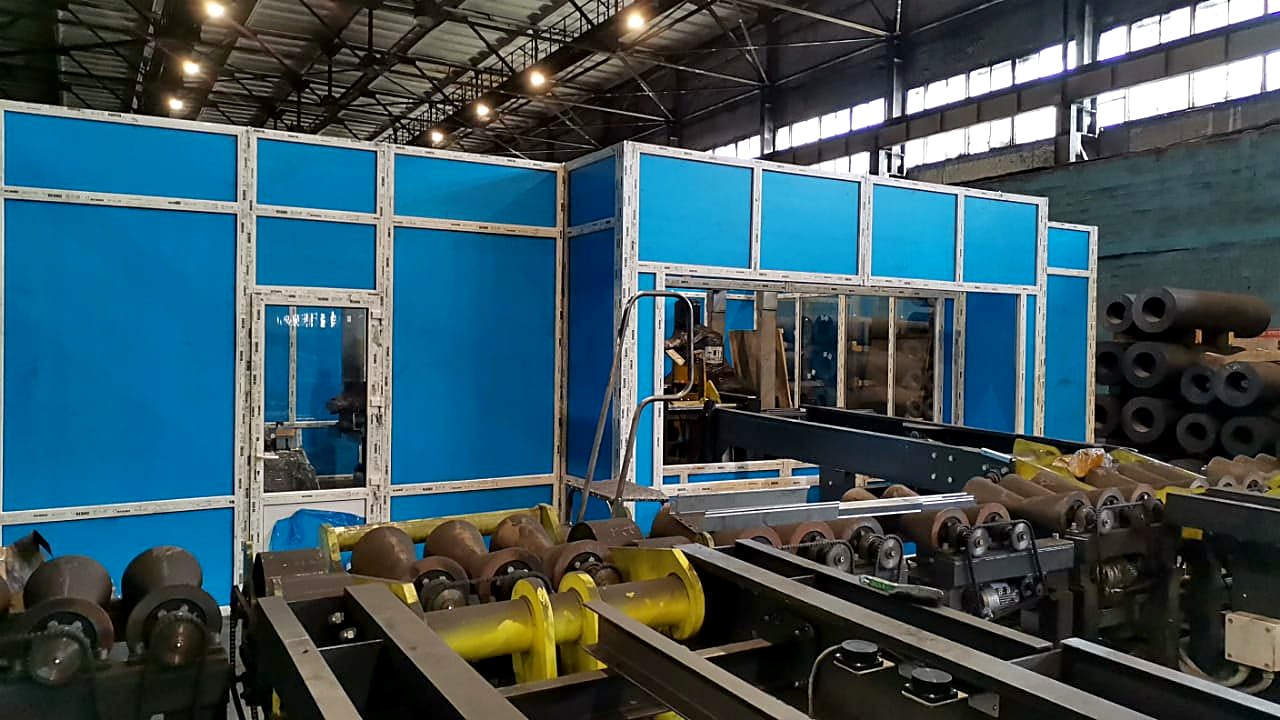
The measuring box is climate-controlled at 20 ± 4 °C, cleaned of graphite dust and kept at overpressure, with two airlocks, so the measuring systems stay stable and free of thermal expansion errors.
ELECTRODE LINE: MEASURING POSITIONS
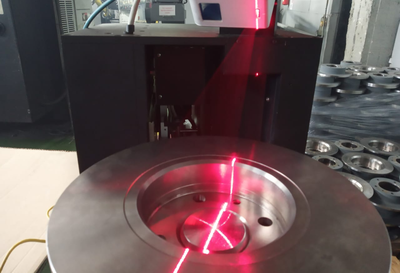
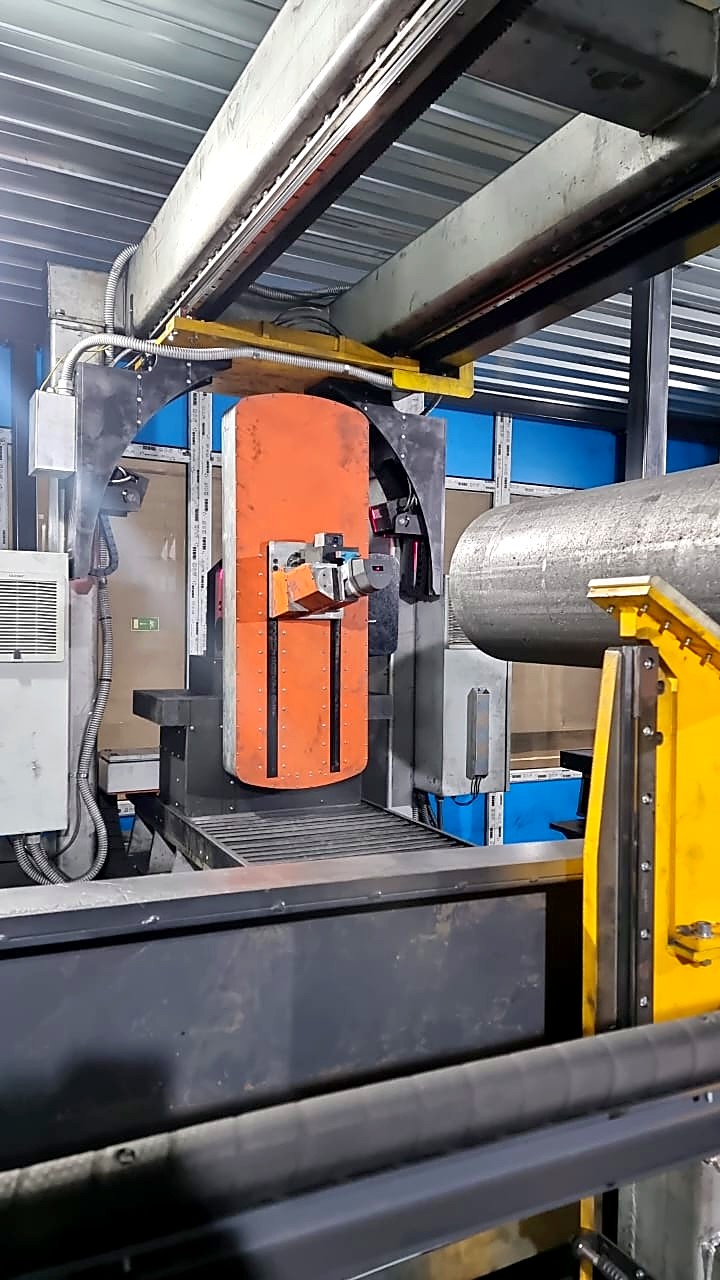
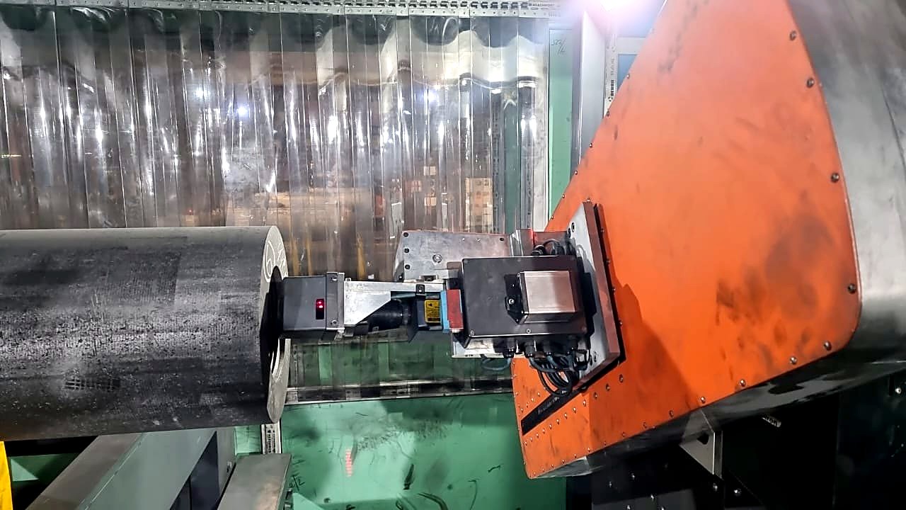
- Laser geometry: two rail-mounted units, one at each end, adjust to electrode lengths from 1500 to 3600 mm and measure the threaded sockets and end faces with a conoscopic laser sensor on a five-axis motion system. At the same time, 2D scanners on an overhead frame scan the electrode body along its length. A colour map of the results shows where the geometry is out of tolerance.
- Weight and resistivity: the electrode is lowered onto load cells to be weighed. Current probes are brought up to the measuring points and into the threaded sockets (potential probes 600 ± 3 mm apart) to measure electrical resistivity. Two ultrasonic sensors, built into the socket probes, measure longitudinal ultrasonic velocity and the dynamic modulus of elasticity.
- Visual inspection: the electrode rolls out of the box and is lifted, and the operator can rotate it with a foot pedal to confirm pass or reject. A label with a bar code and text is printed and applied, and the electrode goes to the pass or reject rack.
ELECTRODES: MEASURED PARAMETERS AND ACCURACY
- thread pitch diameter (200 to 432 mm): ±0.015 mm
- half taper angle: ±17″ for electrodes Ø 500 to 800 mm, ±20″ for Ø 350 to 500 mm
- nipple socket roundness (inner diameter): ±0.02 mm
- thread pitch (between any two adjacent turns): ±0.007 mm
- cumulative pitch deviation over the make-up length: ±0.005 mm
- nipple socket depth (133 to 350 mm): ±0.1 mm
- thread length: ±0.1 mm
- thread profile deviation (tooth width at the pitch line): ±0.005 mm
- end-face flatness (concavity): ±0.01 mm
- end-face perpendicularity to the generatrix: ±0.01 mm
- socket axis perpendicularity to the end face: ±0.01 mm
- coaxiality of thread axis and electrode axis: ±0.1 mm
- electrode length (1500 to 3600 mm): ±1 mm
- electrode diameter (350 to 816 mm): ±0.1 mm
- weight (200 to 3500 kg): ±15 kg
- electrical resistivity (2 to 10 µΩ·m): ±0.1 µΩ·m (target)
- longitudinal ultrasonic velocity: ±1.5%
- dynamic modulus of elasticity (5 to 35 GPa): under 1.5%
ELECTRODE LINE: SPECIFICATION
- electrode sizes: nominal diameter 350 to 800 mm, T4 and T3 connections with N, L and XL nipples
- cycle time: 5 minutes (300 s); laser thread inspection can be set to any interval, e.g. every 10th electrode, for much higher throughput
- changeover between sizes: no more than 10 minutes; none needed on lines built for 400 to 800 mm electrodes
- power: 20 kW, 400 V, 50 Hz
- compressed air: 1.95 m³ per cycle at 5 bar (2.25 Nm³/min at a 5-minute cycle), quality class [7:5:4] to ISO 8573-1
- foundation: standard industrial floor (10 t/m²), with a vibration-isolated foundation under the measuring positions (construction brief provided)
NIPPLE MEASURING COMPLEX: HOW IT WORKS
Two measuring positions are placed beside the belt conveyor or on a gallery above it, within reach of the existing robot. Nipples stand vertically at both positions.
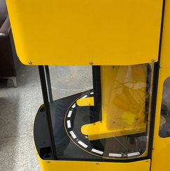
At the first position the robot places the nipple and the complex centres it precisely. An upper probe block descends on a rail and clamps it at a set force, a lower probe block rises from below, and weight, electrical resistivity and ultrasonic properties are measured.
The nipple then moves to a precision rotary table at the laser position. An Optimet ConoProbe laser sensor travels vertically on a frame, scanning the nipple as it rotates. Any number of sections can be scanned, or a spiral path for the most accurate pitch line, taper and pitch diameter. The frame is made of 32NKD Invar, which has zero thermal expansion in the working temperature range.
NIPPLES: MEASURED PARAMETERS AND ACCURACY
- thread pitch diameter D2 (200 to 432 mm): ±0.016 mm
- half taper angle (9°26′ to 9°32′): ±17″ for nipples Ø 500 to 800 mm, ±23″ for Ø 350 to 500 mm
- outer diameter roundness (149 to 434.96 mm): ±0.03 mm
- thread pitch (6.35 to 8.47 mm, between any two adjacent turns): ±0.007 mm
- cumulative pitch deviation over the make-up length: ±0.007 mm
- nipple length L (101 to 685.8 mm): ±0.1 mm
- difference between half-cone lengths (50.5 to 211.5 mm): ±0.1 mm
- thread profile deviation (tooth width at the pitch line): ±0.007 mm
- weight (4 to 200 kg): accuracy class III to GOST R 53228-2008
- electrical resistivity (2 to 10 µΩ·m): ±0.1 µΩ·m (target)
- longitudinal ultrasonic velocity (up to 4000 m/s): ±1.5%
- dynamic modulus of elasticity (3 to 18 GPa): ±2%
NIPPLE COMPLEX: SPECIFICATION
- cycle time: 2 to 4 minutes per nipple at each position, depending on size; designed for 8,000 operating hours a year
- power: 12 kW, 400 V, 50 Hz
- compressed air: 0.5 m³ per cycle at 5 bar (0.75 Nm³/min at a 4-minute cycle), quality class [7:5:4] to ISO 8573-1
AUTOMATION AND SOFTWARE
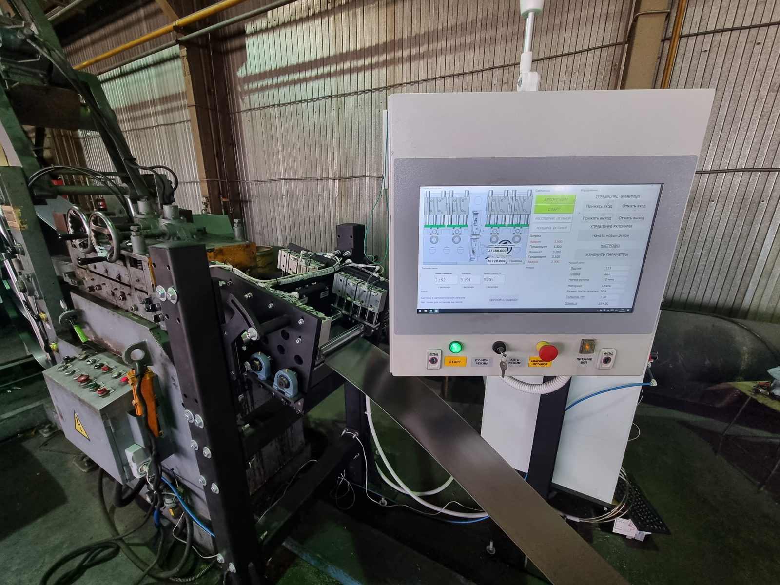
- The equipment sets itself up for each size automatically. The size, its specification with tolerance limits, and the serial number come from the plant's process control system.
- All measurements are saved in the system's local database and are available to the plant's control system. Each part gets a pass/fail flag, also shown by the colour of a signal tower.
- Integration over PROFINET, with a full signal list supplied.
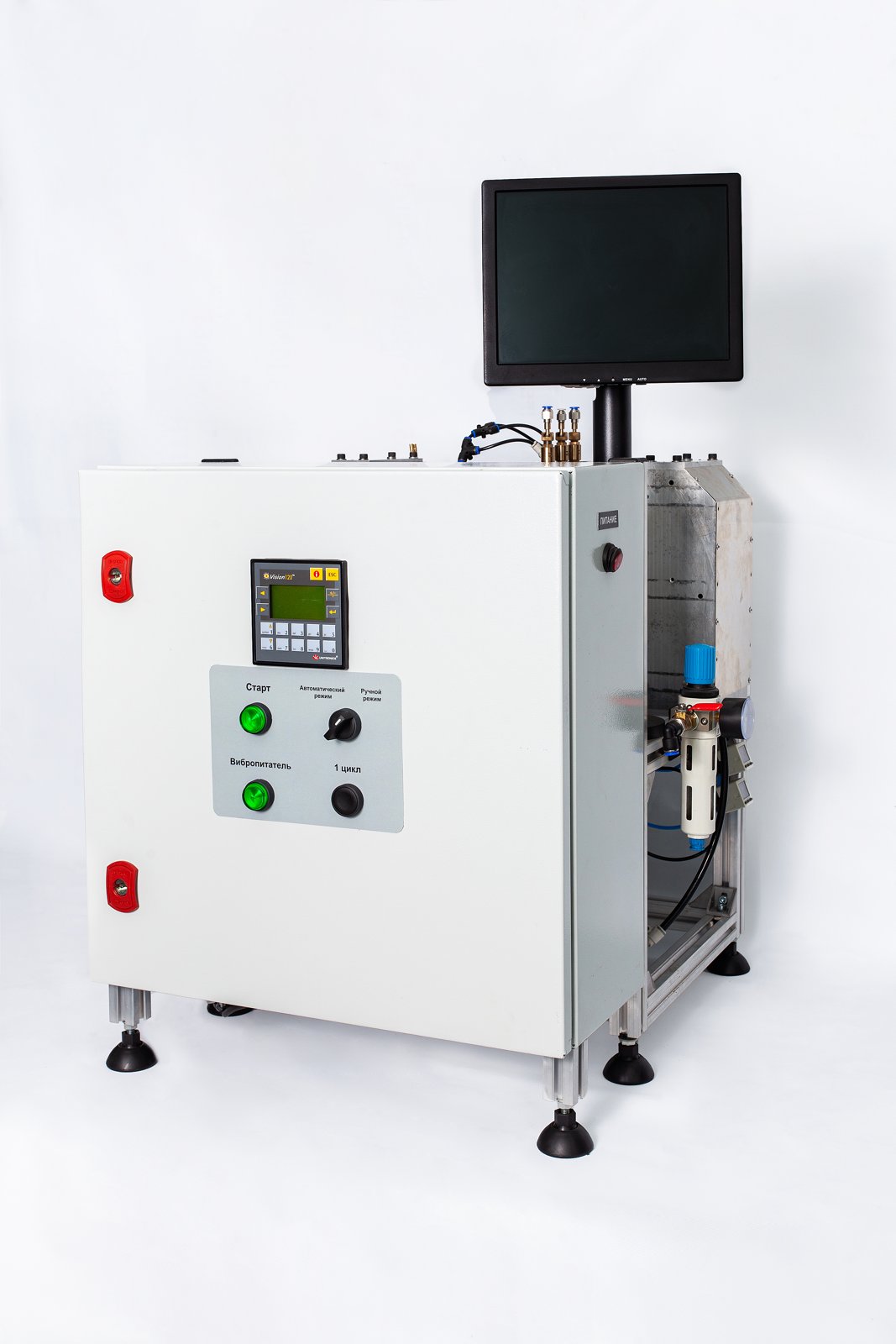
- PLC/HMI and measuring software programming are included, and the source files are handed over.
- UPS for the industrial computers and controllers (at least 10 minutes) to finish the cycle and save the measurements.
SCOPE OF SUPPLY
- input and output racks, and the in-box transport system
- two laser units for threads and end faces, and one laser unit for scanning the electrode body
- equipment for weight, electrical resistivity, ultrasonic velocity and dynamic modulus of elasticity
- label printing and applying station
- temperature-controlled control cabinets, operator consoles, signal towers and emergency stops
- calibration gauges and reference standards for every measuring unit, with calibration and verification procedures
- spare parts for the warranty period
- operating, repair and installation documentation, assembly drawings and an as-built dossier
- design documentation for the climate-controlled measuring box, which the customer builds
- option: input and output racks and a fixing post for an electrode–nipple assembly area
CUSTOM VERSION
The equipment can be adapted to your requirements, and rack length (capacity) is made to order. The standard version uses electromechanical drives. Warranty: 2 years from commissioning.